DIL pitch terminals. High sensitivity :0.14W or 0.10W nominal power.
Conforms to FCC Part 68 1.5kV surge and dielectric 1000VAC.
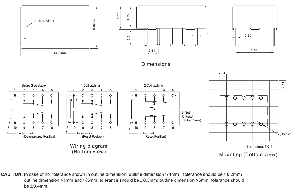
Monostable, single or double coil latching relay .
Application for telecommunication equipment, office equipment, security alarm systems, measuring instruments, medical monitoring equipment, audio visual equipment, flight simulator, sensor control.

1 Part number: P
2 Operating function NIL: Single Side Stable;
L:1 Coil Latching; K:2 Coil Latching
3 Coil rated voltage(V): DC:3,4.5,5,6,9,12,24
4 Contact material: NIL: AgPd; W: AgNi
|
Contact Arrangement |
2C(DPDT(B-M)) (Bifurcated Crossbar) |
||
|
Contact Material |
AgPd(Au plated ) AgNi(Au plated) |
||
|
Contact Rating (resistive) |
1A,2A/30VDC; 0.5A/125VAC |
||
|
Max. Switching Power |
60W 62.5VA |
Min. Switching load:0.01mA/10mV(Reference Value) |
|
|
Max. Switching Voltage |
220VDC 250VAC |
Max. Switching Current:2A |
|
|
Contact Resistance |
≤50mΩ |
Item 4.12 of IEC 61810-7 |
|
|
Operational Life |
Electrical |
2X10⁵(DC AgPd);1X10⁵(DC AgNi) 1X10⁵(AC) |
Item 4.30 of IEC 61810-7 |
|
Mechanical |
1X10⁸ |
Item 4.31 of IEC 61810-7 |
|
|
Dash numbers |
Coil voltage VDC |
Coil resistance Q±10% |
Pick-up voltage VDC(max) (75%of rated voltage ) |
Drop-out voltage VDC(min) (10%of rated voltage) |
Coil power W |
Operate time ms |
Release time ms |
||
|
Rated |
Max. |
||||||||
|
P-003 |
3 |
7.5 |
64.3 |
2.25 |
0.3 |
0.14 |
Approx.2
|
Approx.1
|
|
|
P-004 |
4.5 |
11.25 |
144.6 |
3.38 |
0.45 |
0.14 |
|||
|
P-005 |
5 |
12.5 |
178 |
3.75 |
0.5 |
0.14 |
|||
|
P-006 |
6 |
15.0 |
257 |
4.50 |
0.6 |
0.14 |
|||
|
P-009 |
9 |
22.5 |
579 |
6.75 |
0.9 |
0.14 |
|||
|
P-012 |
12 |
30.0 |
1028 |
9.00 |
1.2 |
0.14 |
|||
|
P-024 |
24 |
48.0 |
2880 |
18.0 |
2.4 |
0.20 |
|||
|
1 Coil Latching |
Set |
Reset(Max) |
|
Set |
Reset |
||||
|
PL-003 |
3 |
8.7 |
90 |
2.25 |
-2.25 |
0.10 |
Approx.2
|
Approx.2
|
|
|
PL-004 |
4.5 |
13.0 |
202.5 |
3.38 |
-3.38 |
0.10 |
|||
|
PL-005 |
5 |
14.5 |
250 |
3.75 |
-3.75 |
0.10 |
|||
|
PL-006 |
6 |
17.4 |
360 |
4.50 |
-4.50 |
0.10 |
|||
|
PL-009 |
9 |
26.1 |
810 |
6.75 |
-6.75 |
0.10 |
|||
|
PL-012 |
12 |
34.8 |
1440 |
9.00 |
-9.00 |
0.10 |
|||
|
PL-024 |
24 |
57.6 |
3840 |
18.0 |
-18.0 |
0.15 |
|||
|
2 Coils Latching |
Set Coil |
ResetCoil |
Set |
Reset(Max) |
|
Set |
Reset |
||
|
PK-003 |
3 |
6 |
45 |
45 |
2.25 |
2.25 |
0.20 |
Approx.2
|
Approx.2
|
|
PK-004 |
4.5 |
9 |
101 |
101 |
3.38 |
3.38 |
0.20 |
||
|
PK-005 |
5 |
10 |
125 |
125 |
3.75 |
3.75 |
0.20 |
||
|
PK-006 |
6 |
12 |
180 |
180 |
4.50 |
4.50 |
0.20 |
||
|
PK-009 |
9 |
18 |
405 |
405 |
6.75 |
6.75 |
0.20 |
||
|
PK-012 |
12 |
24 |
720 |
720 |
9.00 |
9.00 |
0.20 |
||
|
PK-024 |
24 |
36 |
1920 |
1920 |
18.0 |
18.0 |
0.30 |
||
CAUTION:
1.The use of any coil voltage less than the rated coil voltage will compromise the operation of the relay.
2.Pickup and release(reset) voltage are for test purposes only and are not to be used as design criteria.
3.When latching relays are installed in equipment, the set and reset coil should not be powered simultaneously. Coil should not be pulsed with less than the nominal coil voltage and pulse width should be a minimum of three times the specified operate time of the relay. If these conditions are not followed, it is possible for the relay to be in the magne tically neutral position .
|
Electrostatic Capacitance |
|
|
|
Between Open Contacts |
Approx.0.4pF |
Item4.41 of IEC 61810-7 |
|
Between Coil & Contacts |
Approx.0.9pF |
Item 4.41 oflEC 61810-7 |
|
Between Contact Poles |
Approx.0.2pF |
Item 4.41 oflEC 61810-7 |
|
Insulation Resistance |
1000MΩ min(at 500VDC) |
Item 4.11 of IEC 61810-7 |
|
Dielectric Strength |
|
|
|
Between Open Contacts Between Coil & Contacts Between Contact Poles |
1000VAC 1min 1000VAC 1min 1000VAC 1min |
Item 4.9 oflEC 61810-7 |
|
Surge Withstand Voltage |
|
|
|
Between Open Contacts Between Coil & Contacts Between Contact Poles |
1500V 1500V 2500V |
FCC68 |
|
Shock Resistance |
Functional:490m/s² 11ms; Destructive:980 m/s² 6ms |
Item 4.26 oflEC 61810-7 |
|
Vibration Resistance |
10Hz~55Hz Double amplitude Functional: 3mm Destructive:5mm |
Item 4.28 oflEC 61810-7 |
|
TerminalsStrength |
5N |
Item 4.24 oflEC 61810-7 |
|
Temperature Range |
-40℃-70℃(-40° F~158° F) |
|
|
Mass |
Approx. 1.5g |
Item 4.7 oflEC 61810-7 |
|
Safety approval |
UL&CUR |
TUV |
|
Load |
1A,2A/30VDC;0.5A/125VAC |
1A/30VDC;0.5A/125VAC |
Address
NO.13, 125 Lane, Qi-Wen Road, Haishu District, Ningbo, Zhejiang,China
Tel
![]() Ningbo Huaguan Electronics Co., Ltd.
Ningbo Huaguan Electronics Co., Ltd.
![]() NO.13, 125 Lane, Qi-Wen Road, Haishu District, Ningbo, Zhejiang,China
NO.13, 125 Lane, Qi-Wen Road, Haishu District, Ningbo, Zhejiang,China